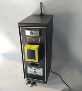
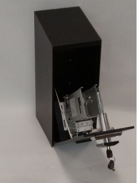
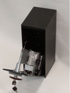
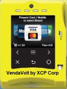
XCP Corp manufactures a Nayax Powered Credit Card Payment Card/Ticket Vendor. The dispenser mechanism is mounted inside of a metal cabinet with a T-handle high security vending lock. The TCD-180M card/ticket dispenser has a capacity of 160 - 180+ normal CR80 size .030 thickness plastic cards. Cards or tickets are dispensed by the Nayax Vpos Touch cashless payment with Visa, MasterCard, Discover and American Express magnetic stripe, chip or RFID credit/debit cards. FCC ID: R17ME910G1WW For The Nayax Vpos Touch. Also payment can be made with Monyx Wallet, Apple Pay and Google Wallet. The card magazine has a low inventory adjustable quantity sensor that illuminates a red LED indicator when the remaining quantity is running low. Powered by a 24VDC 5 amp desk top power supply. Click this link to "Contact Us" for same day reply. Click This Link For The Nayax University Video
Click this link to "Contact Us" for same day reply.
TCD-180M Card Dispenser Technical Information
.jpg?1668785394987)
(Version 1.00)
TCD-180M CONTENTS
1. General description…………………………………………………………………..3
2. Technical description…………………………………………………………………3
3. Control interface………………………………………………………………………4
3.1 Electronic control interface ................................................................................ ..4
3.2 RS232 control interface………………………………………………………….....4
3.3 Control description.............................................................................................. ..5
3.4 Sketch map of circuit........................................................................................... ..6
4. Indication of the working condition of the card/ticket dispenser ....................... ..6
5. Operation and maintenance ................................................................................ ..6
5.1 Installation of the card/ticket dispenser............................................................. ..6
5.2 Removing and replacing the cartridge............................................................... ..7
5.3 Card/Ticket loading............................................................................................. ..7
5.4 Card/Ticket thickness adjustments ................................................................... ..7
5.5 Safety and maintenance..................................................................................... ..8
6. Notice of using safety............................................................................................ ..8
7. Dimensions: 9 inches (225mm) x 3 inches (75mm) x 6.25 inches (160mm), 3.3 pounds
1、Main Description Of The XCP Model TCD-180M Card/Ticket Dispenser Or Optional USPS 20 Stamp Booklet Dispenser Mechanism
³Industrial design for debit/credit card dispensing equipment such as; transit, car washes, library debit cards, parking, laundry, toll debit cards, food services and so on.
³Highly adaptability to various thickness and deformed cards.
³Watchdog of hardware and micro-embedded real-time operating system to ensure reliable operation.
³Pre-dispense function accelerate dispensing speed
³Directly connect to the electronic control system
³Automatic buzzer alarm when card/ticket magazine is full
³Automatic reset after the wrong alarm of 100S is triggered
³RS232 and I/O voltage interface is available.
³The card dispensing mode can be selected for multiple card dispensers.
³Adjustable capacity of card/ticket magazine.
³The card/ticket thickness can be adjusted within 0.2mm―2.4mm (Factory default setting is: 0.8mm/.30)
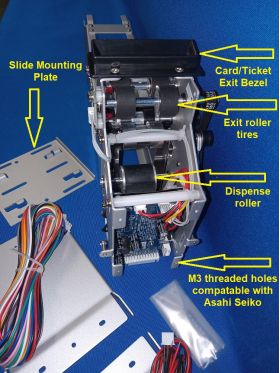
³Main control board slid in design allows for the installation and removal simple, convenient and fast.
³Factory die stamping process in production ensures the products` quality and consistency.
2、Main technology description
³Operating voltage: 24VDC (MAX current2A, static current 0.1A)
Dimensions: 9 inches in height x 3.25 inches in width x 6.5 inches in length from front to back.
Working temperature: -30℃ to 70℃
Working relative humidity: 30-90%
Work condition: installed in bin
Card dimension: width:54 ± 0.5 mm x length: 85 ± 0.5 mm
USPS stamp booklet dimension: 5.5200 inches x 1.9600 inches, 140.2080 mm x 49.7840 mm
Thickness: 0.2 – 2.4 mm(adjusted)(Note:Factory default: 0.8mm/.030)
Material:paper and polyester cards.
Net weight: 1.5Kg – 3.3 pounds(including card weight)
Dispensing time: approximately 0.5S at 24VDC
Card/ticket capacity: 150pcs at 0.8mm - .30 or 300+ at 0.20 – 0.24mm
3、Control interface
I/O and RS232 control interface is available for the TCD-180M card dispenser. I/O control interface is available by the CN3 on the control broad, RS232 control interface is available by the CN7 of Pin 3 (2.54mm)
3.1 Definition of voltage control interface (CN3)
NO. | Signal definition | description |
1 | 0V (24V cathode) | operating voltage cathode |
2 | +24V(24V anode) | operating voltage anode |
3 | 0V(input/output signal) | link with operating voltage anode |
4 | PayOut(card issue signal) | Input, low-level(min 200 ms)effective |
5 | Reset(reset input ) | input,low-level(min 200ms)effective |
6 | 0V (input/output signal) | link with operating voltage cathode |
7 | VD (detector input) | input,low level (min 200ms) effective,can be used as enable signal dialing DIP3 on the control broad to the ON position |
8 | Call Back(reclaim card) | input,low level effective (min 200ms) |
9 | Out OK | Open collect output,Low level effective。When DIP2=OFF, the signal of OUTOK is that card is in the reading place or in taken place;when DIP2=ON,OUTOK will input 300ms impulse after the card is taken away. Otherwise not any signal will be output in the process of dispensing the card. |
10 | Lower | Open collector output, low level effective。 |
11 | Error | Open collector output, low level effective 。 |
12 | Empty | Open collector output, low level effective。 |
3.2 RS232 control interface definition (CN7)
NO. | signal definition | description |
1 | GND | signal ground |
2 | RXD | RS232 series receiving terminal |
3 | TXD | RS232 series sending terminal |
9600bps baud rate is used by Communication of RS232 interface 9600bps,8 data bit,2stop bit,no parity calibration bit. And the software is used the SDPP of our company. More detail information please see the <
3.3 control description
1、Reset
When the card dispenser resets, the first "beep" "beep" is for self-inspection。If everything is in the normal operating condition, the card dispenser will drive the motor rotation forward for the normal pre-card dispenser operation. The following condition will lead to a card dispenser reset condition.:
① Power "On";
② The card dispenser received a reset signal or press of a button on the control panel;
③ Error outputs over 100 seconds.
2、Errors during output and processing
There are two situations that will lead to an error output condition:
① When Pre-dispense failure will send a signal for the "beep" "beep" "beep" for three short beeps or toots;
② When a checked card is jammed (buzzer beep signal for the "beep" "beep" short beeps.
③ When an ERROR signal is detected, the card dispenser will reset and clear the signal of error after 100S;In normal circumstances after reset the overtime errors can be cleared, the jammed cards can be automatically recovered, but when the magazine recovery is full, it will continue to send the error signal. Therefore, the user should remind operators to check whether the card/ticket magazine is full or has a different fault.
3、OUTOK output mode setting
There are two ways for OUTOK signal outputs set by the DIP2 of CN9。When DIP2=ON,OUTOK output will accept a card/ticket signal,or when the card/ticket was removed,low level impulse of 300mS will be output;When DIP2=OFF, OUTOK will output a card/ticket ready signal. This will show the card/ticket was sent to the card reader position or removed location.
4、Dispense mode setting
There are two dispenser modes including whole card/ticket dispensing and half card/ticket dispensing which were set by the DIP1 of CN9 on the control broad.
Whole card/ticket dispensing mode: when DIP1=ON,input payout signal and VD signal is effective under the whole card/ticket dispensing mode. The card will be sent to the reader location and prepare to dispensing card again.
Half card/ticket dispensing mode: when DIP1=OFF,input payout signal and VD signal is effective under the half card/ticket dispensing mode. The card will be sent to the front-wheel drive and press the terminal end waiting for removed away.
3.4sketch map of I/O voltage control interface
4、Working conditions and indications of the card/ticket dispenser
The red LED of the control broad in the card dispenser indicates Voltage status. The several buzzer "beeps" output shows all the various states of the card/ticket dispenser.
NO. | Work condition of card dispenser | Buzzer output | Port output |
1 | reset | Consecutive ring "beep, beep" | no |
2 | Missing card(can dispense card) | "Beep" Interval ring "beep" | Lower |
3 | Jammed card/ticket (cannot dispense card/ticket) | Interval ring" beep ""beep" | Error |
4 | Overtime error (cannot dispense card) | Interval ring "beep、beep、beep" | |
5 | Empty | Interval ring "beep or toot, beep or toot、beep or toot、beep or toot、beep or toot" | Empty |
5、Operation and maintenance
5.1 Installation
You can install the card/ticket dispenser in the cabinet in accordance with the following method:
Making two installing holes with the diameter of 3mm on the appropriate place to the center line of the mother broad refer to which on the guide rail track bracket. Then the guide rail track bracket should be fixed on the mother broad of the cartridge with appropriate distance ,insert the dispenser into the broad of the guide rail track bracket and the two screws should be fixed on the two sides of the card/ticket dispenser as the last step. The card dispenser installation is finished. Insert the 1x12 signal line plug into the socket at the rear of the card/ticket dispenser. The card/ticket dispenser is now installed and can be checked on power "on" condition.
5.2 Removing the card/ticket dispenser
The card/ticket dispenser can be removed from the unit when debugging or maintenance by removing the power from the unit and opening the cabinet where it is installed. Carefully remove the 1x12 plug from the circuit board. Loosen the 2 screws and move the card/ticket dispenser along with guide rail track bracket.
5.3 Card/ticket loading
When the buzzer is signaling for the card/ticket magazine being empty or low of inventory at that time the operator should add additional card/tickets to ensure the normal operation of the card/ticket dispenser system.。
1、Important! Make sure the added card/ticket thickness is matching with the preset adjustment of the card/ticket dispenser mechanism. Please contact the management as soon as possible if the card thickness is not in accordance with the preset setting of the card/dispenser, Note: un-trained people should not be allowed to calibrate the thickness of the card/tickets.)。
2、The steps of loading card/tickets:
Open the card/ticket cabinet, remove the power, take out the card/ticket weight from the card/ticket dispenser magazine, then place cards or tickets into the magazine. Next, place the card weight on the top of the loaded card/tickets as the last step. Turn back "on" the power and close the door of the cabinet.
5.4 Thicknesses adjusting of card dispenser
The thickness of card/ticket dispenser can be adjusted to match the thickness of the card or ticket. The adjusted condition of the thickness will affect the complete performance of the card/ticket dispenser. An untrained person should not be permitted to adjust the thickness of the card or ticket.
The main focus of adjusting the thickness of the card is the adjusting of the clearance between the upper separation wheel and the lower bottom separation wheel. The principles of adjusting the card thickness is to make sure the clearance is 1.5 times to the specified card/ticket. The clearance must be the same across from side to side.
The detail for adjusting the clearance :
First step is loosening the tightener of the strap on the upper separation wheel, the two screws on the top of the adjustment should be backed out 1-2mm, and then loosening the four screws on the two sides of the adjustments brackets, selecting the appropriate card and insert into the clearance of the upper separation wheel and the lower separation wheel. Use both hands to adjust the two sides of the adjustment brackets lightly. Make sure the upper separation wheel and the lower separation wheel are equal in height. Tighten the four screws on the two sides of the adjustment brackets and on the top of the adjustment brackets. Load 30 cards or tickets at least and inspection on up. Check that the card/ticket is not being held back or that more than 1 card/ticket is dispensed. When all if checked and functional, drop a spot of glue on all screws and recording the thickness of the card on a card or label to be placed on the side of the card/ticket dispenser. Now the card/ticket dispenser can be used again. If the thickness of the card or ticket is changed, it should be readjusted again. Thickness of the plug gauge for reference is listed below in milimeters:
Card thickness | 2.2 | 1.8 | 1.5 | 1.2 | 1.0 | 0.8 | 0.6 |
Plug gauge thickness | 2.8~3.4 | 2.3~2.8 | 1.8~2.2 | 1.5~1.8 | 1.4~1.6 | 1.1~1.3 | 0.8~1.0 |
5.5 The normal maintenance and safety
The following situation will appear after the card/ticket dispenser has been used in a period of time or the number of card/tickets has changed the gauge of the distance between the upper and lower rollers:
a) The card/ticket does not dispense until the motor has been running for several times.
b) If the card/ticket is not dispensed after running five times and buzzer ring for the "beep" "beep" "beep" three short beeps.
The following maintenance work should be implemented immediately:
1、Wipe the surface of the clutch roller(at the base of card magazine) with an alcohol-impregnated cloth or pad.
2、Identify the cards or tickets which may have oil on the surface or are deformed seriously。After being cleared by the cloth with alcohol-impregnated, the card or tickets can be used again. After being repaired, if the card cannot be used, the it should be discarded.
3、Check every part of the card/ticket dispensing machine checking to see if the machine is loose or has any other negative condition or not. If a negative operational condition exists, advise management personnel immediately.
6、Safety using notice
1、Control circuitry must be disconnected from electrical power to the mechanism when the host machine/cabinet is opened for servicing.
2、Inserting or dialing the port connection socket which may damage the control circuit
3、Any liquid spilled on the card/dispenser mechanism should be avoided.
4、Servicing and maintenance staff must be adequately trained and aware of the hazards presented by the rollers and drive belts. The motor drives through a reduction gear creating sufficient torque to trap fingers, hair and clothing of the unwary person.
5、Never hold the dispenser by the magazine alone as it could become detached ,allowing the machine to fall which may cause possible injury or damage.
6、Avoid the inclusion of foreign objects such as; liquid, tape, rubber bands and wire as these could cause the machine to jam or short circuit the electronics of the control board.
7、Keep the card/ticket dispenser mechanism clear of contaminants. Oily adhesive substance will seriously affect the performance of the dispenser mechanism.
Click this link to "Contact Us" for same day reply.
.jpg?t=1741105776)
.jpg?t=1741105776)

.jpg?t=1741105776)


.jpg?t=1741105776)